S-RTK GNSS High-Precision Positioning and Heading System
S-RTK GNSS®
Version: V1.1
Translation status: English draft; pending technical review.
This manual is intended solely for the installation, configuration and operation of S-RTK GNSS products.
Reading this manual
- We recommend watching the official tutorial videos first.
- Then read this manual and the documentation supplied with the product.
- If you have questions, contact SINAVE technical support.
English draft — technical review pending. Some illustrations are Chinese placeholders awaiting replacement.
Product overview
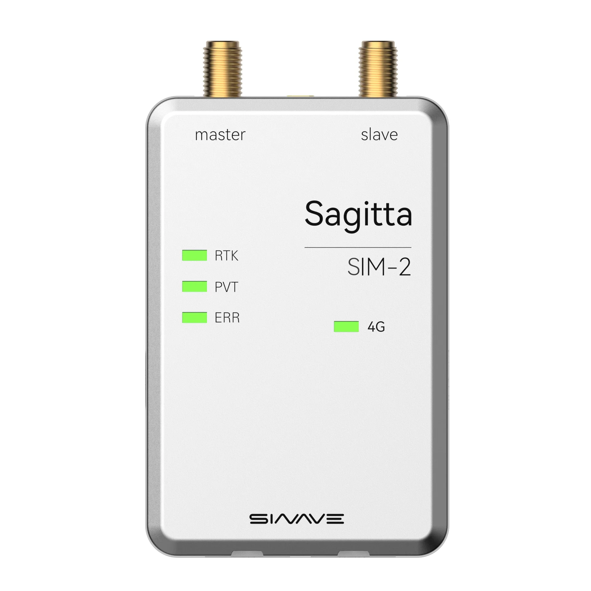
S-RTK GNSS combines high-precision RTK positioning with dual-antenna heading determination. It accepts serial RTCM correction data and supports 4G CORS network RTK, providing centimeter-level positioning and reliable heading solutions.
Designed for demanding outdoor applications, the module supports mobile robotic systems such as drones, humanoid robots, quadruped robots and autonomous vehicles. Its DroneCAN, UART and MQTT interfaces simplify system integration across platforms.
Specifications
| Item | Category | Specification |
|---|---|---|
| Constellations | BDS / GPS / GLONASS / Galileo / QZSS | |
| Master / Slave antenna frequencies | BDS | B1I, B2I, B3I |
| GPS | L1C/A, L2P(Y), L2C, L5 | |
| GLONASS | G1, G2 | |
| Galileo | E1, E5a, E5b | |
| QZSS | L1, L2, L5 | |
| Positioning accuracy | Standalone positioning (RMS) | Horizontal: 1.5 m Vertical: 2.5 m |
| DGPS | Horizontal: 0.4 m + 1 ppm Vertical: 0.8 m + 1 ppm |
|
| RTK | Horizontal: 0.8 cm + 1 ppm Vertical: 1.5 cm + 1 ppm |
|
| PPP | Horizontal: 5 cm Vertical: 10 cm |
|
| Heading accuracy (RMS) | 0.1° / 1 m baseline | |
| PPS accuracy (RMS) | 20 ns | |
| Velocity accuracy (RMS) | 0.03 m/s | |
| Time to first fix | Cold start | < 30 s |
| Hot start | < 4 s | |
| Data update rate | Configurable using the configuration software | Default: 10 Hz; maximum: 20 Hz |
Interface definitions
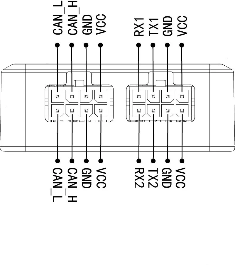
The module provides CAN and UART interfaces as shown in the diagram. The two pairs of CAN signal wires are connected internally, making it convenient to connect additional CAN devices. If the module is at the end of the CAN bus, the source manual recommends connecting a 120-ohm termination resistor to the unused pair of CAN signal wires.
The VCC wires are connected internally, as are the GND wires. Only one external power input may be connected at a time. The spare power wires can supply other devices. Serial port 1 outputs positioning data, and serial port 2 carries RTCM data.
| Name | Definition | Notes |
|---|---|---|
| VCC | Positive power supply | 5–16 V; must not exceed 18 V |
| GND | Power ground | Also serves as signal ground |
| CAN_H | CAN bus H | Standard CAN signal |
| CAN_L | CAN bus L | Standard CAN signal |
| TX1 | Serial port 1 transmit | 3.3 V TTL; add a series current-limiting resistor if the external interface uses 5 V TTL |
| RX1 | Serial port 1 receive | 3.3 V TTL; add a series current-limiting resistor if the external interface uses 5 V TTL |
| TX2 | Serial port 2 transmit | 3.3 V TTL; add a series current-limiting resistor if the external interface uses 5 V TTL |
| RX2 | Serial port 2 receive | 3.3 V TTL; add a series current-limiting resistor if the external interface uses 5 V TTL |
Parameter configuration
Use the supplied configuration software to set module parameters. Connect the RTK module to a computer through its Type-C port. Run RTK-Manager.exe, select the correct port and open the serial connection. Once connected, switch to the configuration page and click Read parameters to retrieve the module settings.
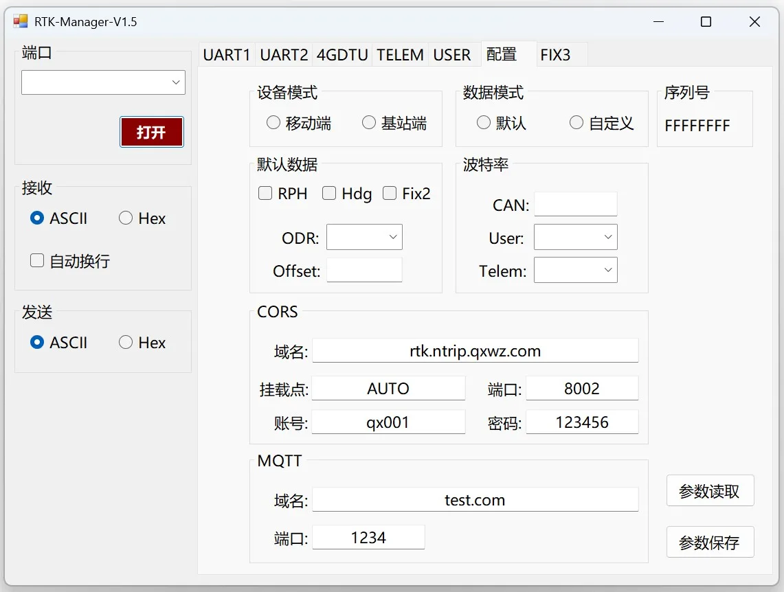 Chinese image placeholder. English replacement pending.
Parameter descriptions
-
Device mode The module can operate as a Rover or Base station. For normal use, we recommend keeping the existing setting.
-
Data mode Choose Default or Custom mode. This setting affects serial output only; CAN output is unaffected.
- Default data: Fix3 format.
- Custom data: direct output from the UM982. Users can select the UM982 output messages.
-
Default data Three data types can be enabled or disabled. These options affect CAN output only; serial output is unaffected. We recommend keeping the RPH, Hdg and Fix2 settings unchanged.
- ODR: data update rate, up to 20 Hz.
- Offset: dual-antenna heading offset.
-
Baud rate Set the baud rates for CAN, the user serial port (serial port 1) and the radio serial port (serial port 2) independently.
-
CORS Configure the connection used to obtain RTK correction data over the 4G network.
-
MQTT An MQTT interface is provided for transmitting key information, including position and heading, to a remote server.
⚠️ Note
- After entering a new value in a text input field such as a CORS account, press Enter each time to write it to the module.
- A Write successful message appears when the write succeeds.
- After configuring all parameters, click Save parameters.
- Unsaved changes are lost after a power cycle; the module reverts to the previously saved configuration.
Custom mode
Set Data mode to Custom and configure the user baud rate to match the rate used by your application. Save the parameters, then power-cycle the module.
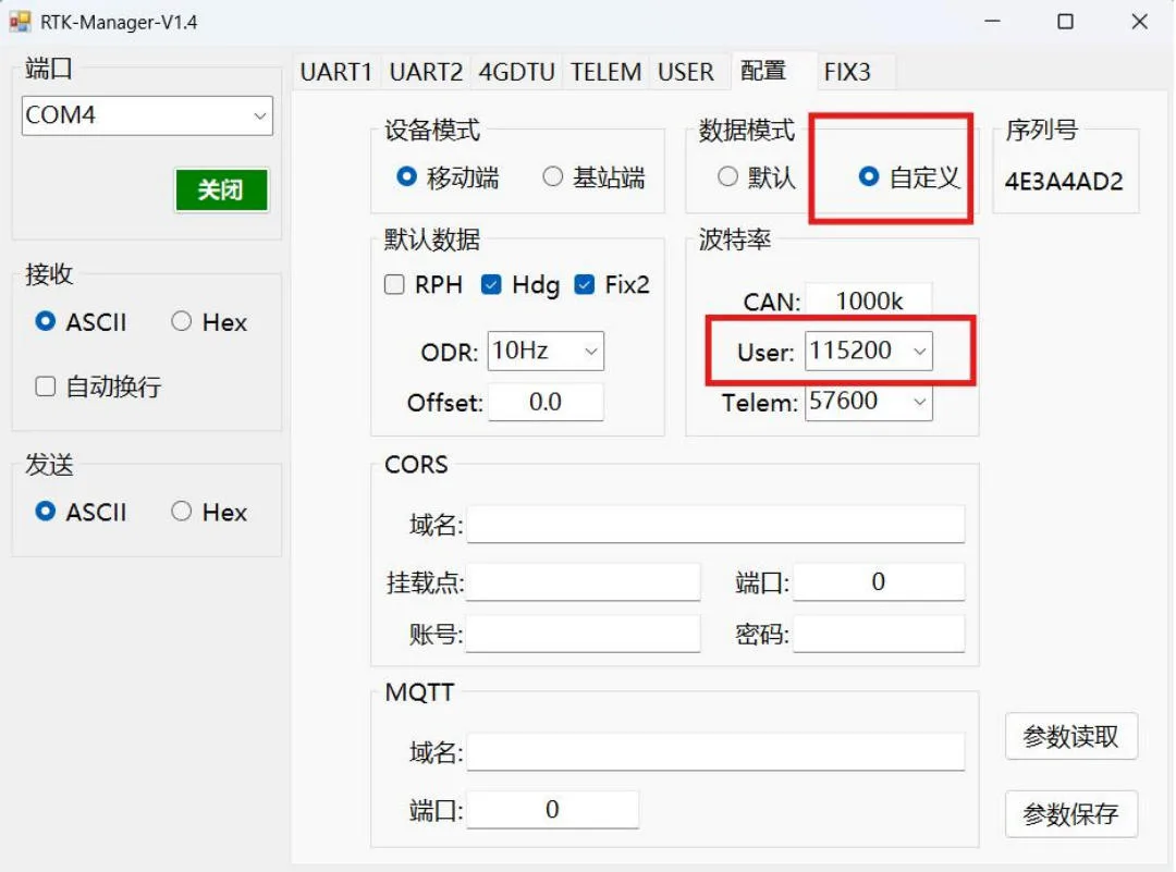 Chinese image placeholder. English replacement pending.
After restarting, open the UART1 page and send the required configuration commands.
To output GPGGA at 1 Hz, send GPGGA 1. The value 1 is the interval in seconds, corresponding to 1 Hz.
To output GPGGA at 10 Hz, send GPGGA 0.1. The value 0.1 is the interval in seconds, corresponding to 10 Hz.
Once the command succeeds, the output data becomes visible and the same data is sent through serial port 1. To retain the configuration, send SAVECONFIG.
Every command must end with a carriage return.
Installation and calibration
Installation

 Chinese image placeholder. English replacement pending.
 Chinese image placeholder. English replacement pending.
-
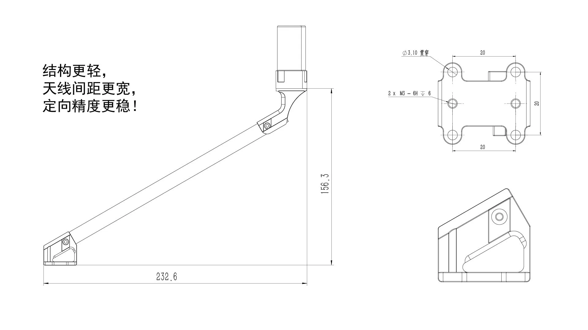
Position the antennas Use the widest antenna separation practical for the aircraft or robot. A Master-to-Slave separation of at least 25 cm is recommended for optimal heading performance.
-
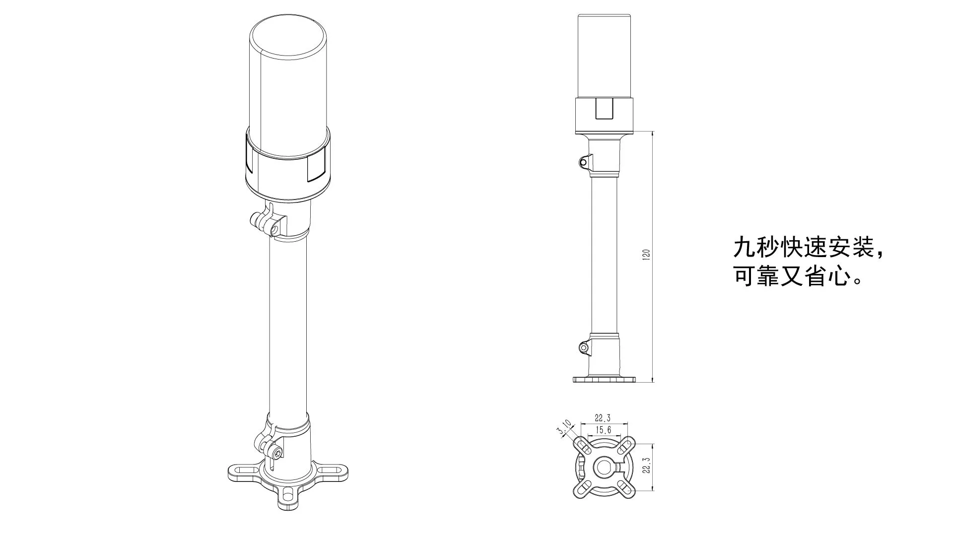
Secure the antennas Install the antenna brackets, then screw the helical antennas firmly into place.
-
Secure the module Attach the S-RTK GNSS module to the platform using double-sided adhesive tape. Prevent vibration and loosening.
-
Connect communications Connect the module to the main controller through CAN or UART, as required by the controller.
Offset settings
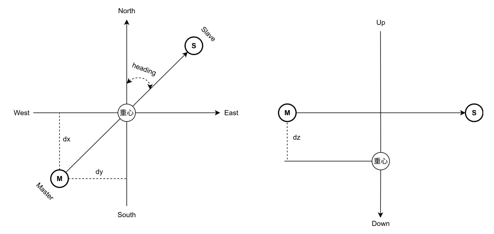
Position is referenced primarily to the Master antenna. Heading is the angle between true north and the vector from the Master antenna to the Slave antenna. When setting the position offset, use the Master antenna as the reference. The module uses the NED coordinate system by default:
- North offset (dx): positive; south offset (dx): negative.
- Right offset (dy): positive; left offset (dy): negative.
- Down offset (dz): positive; up offset (dz): negative.
 Chinese image placeholder. English replacement pending.
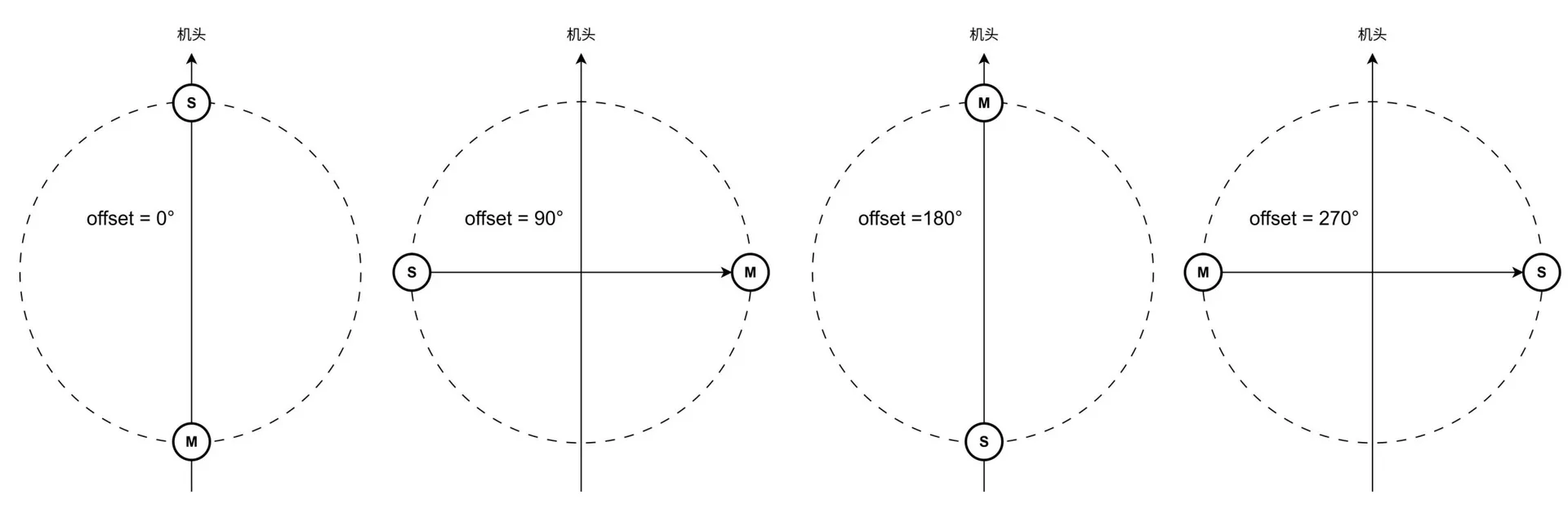
Normally, install the Master antenna directly behind the Slave antenna, with the Slave antenna at the front. The module's heading then matches the platform's forward direction.
If installation constraints require rotating the antenna baseline, set the heading offset to the counterclockwise angle from the Master-to-Slave direction to the platform's forward direction. The following diagram shows four typical arrangements and their heading offsets.
Set the heading offset in RTK Manager. See the description of Default data in Parameter configuration and set the Offset value.
 Chinese image placeholder. English replacement pending.
DroneCAN flight controller configuration
The module's CAN interface uses DroneCAN to connect to common open-source flight controllers. The following sections describe configuration for controllers running APM and PX4 firmware.
APM firmware configuration (MissionPlanner, firmware 4.6 and later)
CAN_P1_DRIVER = 1 (Enable the CAN1 driver)

GPS_AUTO_CONFIG = 0 (Disable automatic DroneCAN GPS configuration; the module is factory-configured, so keeping this disabled is recommended)

GPS1_TYPE = 9 (Set GPS type to **DroneCAN**)

GPS1_POS_X:Master antenna [X-axis] offset dx from the center of gravity (forward positive, rearward negative)

GPS1_POS_Y:Master antenna [Y-axis] offset dy from the center of gravity (right positive, left negative)

GPS1_POS_Z:Master antenna [Z-axis] offset dz from the center of gravity (down positive, up negative)

EK2_SRC1_YAW = 2 / 3
   - 2: Use GPS as the only heading source
   - 3: Use GPS preferentially, with the compass as backup
PX4 firmware configuration (QGC)
UAVCAN_ENABLE = "Sensors Automatic Config" (Enable automatic UAVCAN sensor configuration)

EKF2_GPS_CTRL = 15 (Use dual-antenna heading as the heading source)

EKF2_GPS_POS_X:Master antenna [X-axis] offset dx from the center of gravity (forward positive, rearward negative)

EKF2_GPS_POS_Y:Master antenna [Y-axis] offset dy from the center of gravity (right positive, left negative)

EKF2_GPS_POS_Z:Master antenna [Z-axis] offset dz from the center of gravity (down positive, up negative)

EKF2_MAG_TYPE = None / Init
  - None: Do not use the electronic compass
  - Init: Use the electronic compass only to initialize heading
System checks and troubleshooting
Installation and component checks
- Check that the S-RTK GNSS module is installed correctly and securely.
- Check that the communication cables and antennas are connected correctly and securely.
Operating status checks
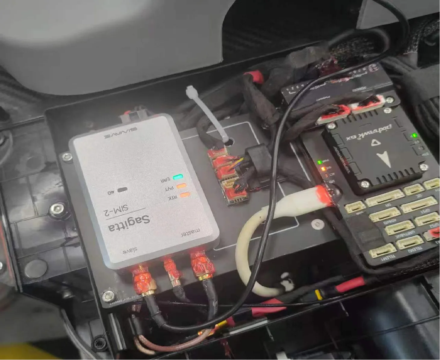
- Check that the LED indicators match the current operating status.
- Check the helical antenna separation and the Master / Slave antenna positions.
- In the ground station software, check whether RTK has achieved a fixed solution (RTK Fixed).
LED quick reference
| Indicator | Steady green | Steady red |
|---|---|---|
| RTK | RTK fixed solution; high-precision positioning output | No RTK fixed solution; standard positioning output |
| PVT | Position fix available; standard positioning output | No position fix; no valid positioning information |
| ERR | Normal operation | System fault |
Common problems and solutions
| Problem | Solution |
|---|---|
| PVT LED is red | Too few satellites are being received. Check for major obstructions and test at a different location. |
| Satellite signals cannot be received indoors. Test outdoors. | |
| RTK LED is red and no fixed solution is obtained | Check that the SMA connectors are tight and the RF cables are intact. RF cables are fragile; do not bend them to a small radius. |
| Swap the Slave and Master antennas to determine whether an RF cable is damaged. | |
| Check the CORS account entries. Press Enter after each entry and confirm that the Write successful message appears. | |
| Keep the area within 45° of the helical antenna as clear of obstructions as possible; obstructions affect satellite reception. | |
| The IoT SIM includes 2 GB of free data per month. If it is used up, the allowance resets the following month. Replace the SIM and test again. | |
| Serial terminal displays garbled data | Do not use the Type-C port to decode Fix3. It is the PC configuration/debug port. |
| Use serial port 1. Connect it to a PC through a USB-to-TTL adapter to inspect the output. The signal level must be 3.3 VDC; add a series current-limiting resistor for 5 V TTL. | |
| Replace the Type-C cable and test again. | |
| RTK LED turns off while the robot moves and recovers when it stops | Check whether the SMA cable at the Master connector is damaged by excessive bending or whether the connector is loose. |
| Swap the Slave and Master antennas to determine whether an RF cable is damaged. |
GNSS_FIX3 data protocol
| Region | Field | Data type | Start byte | Length (bytes) | Description |
|---|---|---|---|---|---|
| Header | head1 | uint8 | 1 | 1 | Frame header |
| Header | head2 | uint8 | 2 | 1 | Frame header |
| Header | id | uint16 | 3 | 2 | Message ID |
| Header | addr | uint16 | 5 | 2 | Message address |
| Header | len | uint16 | 7 | 2 | Length field: the most significant bit, len[15], indicates whether a data payload is present; len[14:0] specifies its length.• len[15] = 1: data is present; length is len[14:0].• len[15] = 0: no data; length is 0. |
| Header | check | uint16 | 9 | 2 | Checksum: sum all bytes except the check field and retain the uint16 result. |
| Payload | data | See message definition | 11 | len[14:0] as specified |
Payload length is 0 when len[15] = 0. |
| Region | Field | Data type | Start byte | Length (bytes) | Value / bytes | Description |
|---|---|---|---|---|---|---|
| Header | head1 | uint8 | 1 | 1 | 0xFA | Frame header |
| head2 | uint8 | 2 | 1 | 0xAA | Frame header | |
| id | uint16 | 3 | 2 | 0x0427 | Message ID = 1063 | |
| addr | uint16 | 5 | 2 | 0x0000 | Message address 0 | |
| len | uint16 | 7 | 2 | 0x803F | Payload length: 63 bytes. | |
| check | uint16 | 9 | 2 | B9~B10 | Sum all bytes except check and retain the uint16 result. | |
| Payload | gps_time | uint64 | 11 | 8 | B11~B18 | UTC timestamp in μs since 1970-01-01 00:00:00. Add the time-zone offset for local time. |
| lon | int40 | 19 | 5 | B19~B23 | Longitude, 8 decimal places; encoded value = degrees × 10^8; unit: 0.00000001°. | |
| lat | int40 | 24 | 5 | B24~B28 | Latitude, 8 decimal places; encoded value = degrees × 10^8; unit: 0.00000001°. | |
| alt | int24 | 29 | 3 | B29~B31 | Altitude, 3 decimal places; encoded value = meters × 1000; unit: mm. | |
| vel_n | int32 | 32 | 4 | B32~B35 | North velocity, 3 decimal places; encoded value = m/s × 1000; unit: mm/s. | |
| vel_e | int32 | 36 | 4 | B36~B39 | East velocity, 3 decimal places; encoded value = m/s × 1000; unit: mm/s. | |
| vel_d | int32 | 40 | 4 | B40~B43 | Down velocity, 3 decimal places; encoded value = m/s × 1000; unit: mm/s. | |
| heading | int16 | 44 | 2 | B44~B45 | Dual-antenna heading, 2 decimal places; encoded value = degrees × 100; range: [-180, 180]; invalid value: 32767. | |
| heading_acc | uint16 | 46 | 2 | B46~B47 | Dual-antenna heading accuracy, 2 decimal places; encoded value = degrees × 100; range: [0, 360]; invalid value: 32767. | |
| pos_n_acc | uint24 | 48 | 3 | B48~B50 | North position accuracy, 3 decimal places; encoded value scaled by 1000; unit: mm. | |
| pos_e_acc | uint24 | 51 | 3 | B51~B53 | East position accuracy, 3 decimal places; encoded value scaled by 1000; unit: mm. | |
| pos_d_acc | uint24 | 54 | 3 | B54~B56 | Down position accuracy, 3 decimal places; encoded value scaled by 1000; unit: mm. | |
| vel_n_acc | uint24 | 57 | 3 | B57~B59 | North velocity accuracy, 3 decimal places; encoded value scaled by 1000; unit: mm/s. | |
| vel_e_acc | uint24 | 60 | 3 | B60~B62 | East velocity accuracy, 3 decimal places; encoded value scaled by 1000; unit: mm/s. | |
| vel_d_acc | uint24 | 63 | 3 | B63~B65 | Down velocity accuracy, 3 decimal places; encoded value scaled by 1000; unit: mm/s. | |
| pdop | uint16 | 66 | 2 | B66~B67 | Position dilution of precision, 1 decimal place; encoded value scaled by 10; unit: 0.1. | |
| vdop | uint16 | 68 | 2 | B68~B69 | Velocity dilution of precision (description retained from the Chinese source), 1 decimal place; encoded value scaled by 10; unit: 0.1. | |
| hdop | uint16 | 70 | 2 | B70~B71 | Vertical dilution of precision (description retained from the Chinese source), 1 decimal place; encoded value scaled by 10; unit: 0.1. | |
| sats_used | uint8 | 72 | 1 | B72 | Number of satellites used. | |
| fix_type | uint8 | 73 | 1 | B73 | Positioning status: 0 invalid, 1 standalone, 2 differential, 3 PPP, 4 RTK FLOAT, 5 RTK FIXED. |
C/C++ parsing example
#include <stdint.h>

uint64_t val;
int64_t lon;

/*
 * Raw bytes (little-endian):
 * 98 DE BE 6B 02
 */
val = ((uint64_t)0x02 << 56)
    + ((uint64_t)0x6B << 48)
    + ((uint64_t)0xBE << 40)
    + ((uint64_t)0xDE << 32)
    + ((uint64_t)0x98 << 24);

/* Shift right by 24 bits to obtain a signed 40-bit integer */
lon = (int64_t)val >> 24;
Notes
- All fields use little-endian byte order.
- Assemble bytes as unsigned integers first.
- For signed data, convert the assembled value to a signed integer afterwards.
- The longitude and latitude fields in this example are 40-bit signed integers. Scale the decoded values according to the protocol to obtain physical values.
Python parsing example
import datetime


def read_uint16_le(b, p):
    return int.from_bytes(b[p:p + 2], "little", signed=False)


def read_uint24_le(b, p):
    return b[p] | (b[p + 1] << 8) | (b[p + 2] << 16)


def read_int24_le(b, p):
    v = read_uint24_le(b, p)
    return v - (1 << 24) if v & 0x800000 else v


def read_uint40_le(b, p):
    return (
        b[p]
        | (b[p + 1] << 8)
        | (b[p + 2] << 16)
        | (b[p + 3] << 24)
        | (b[p + 4] << 32)
    )


def read_int40_le(b, p):
    v = read_uint40_le(b, p)
    return v - (1 << 40) if (v & (1 << 39)) else v


def checksum16(data: bytes) -> int:
    return sum(data) & 0xFFFF


def parse_ulink_frame(frame: bytes):
    if len(frame) < 11:
        raise ValueError("Frame too short")

    if frame[0] != 0xFA or frame[1] != 0xAA:
        raise ValueError("Invalid frame header")

    msg_id = read_uint16_le(frame, 2)
    addr = read_uint16_le(frame, 4)
    len_raw = read_uint16_le(frame, 6)

    has_data = bool(len_raw & 0x8000)
    data_len = (len_raw & 0x7FFF) if has_data else 0

    total_len = 11 + data_len
    if len(frame) < total_len:
        raise ValueError("Frame length mismatch")

    check = read_uint16_le(frame, 8)
    calc = checksum16(frame[:8] + frame[10:10 + data_len])
    check_ok = (check == calc)

    data = frame[10:10 + data_len] if has_data else b""

    return {
        "id": msg_id,
        "addr": addr,
        "data_len": data_len,
        "check_ok": check_ok,
        "data": data,
        "total_len": total_len,
    }


def parse_gnss_fix3(data: bytes):
    if len(data) != 63:
        raise ValueError("GNSS_FIX3 payload length error")

    gps_time_us = int.from_bytes(data[0:8], "little", signed=False)
    gps_utc = datetime.datetime(1970, 1, 1) + datetime.timedelta(
        microseconds=gps_time_us
    )

    lon = read_int40_le(data, 8) / 1e8
    lat = read_int40_le(data, 13) / 1e8
    alt = read_int24_le(data, 18) / 1000.0

    vn = int.from_bytes(data[21:25], "little", signed=True) / 1000.0
    ve = int.from_bytes(data[25:29], "little", signed=True) / 1000.0
    vd = int.from_bytes(data[29:33], "little", signed=True) / 1000.0

    heading_raw = int.from_bytes(data[33:35], "little", signed=True)
    heading = None if heading_raw == 32767 else heading_raw / 100.0

    heading_acc_raw = int.from_bytes(data[35:37], "little", signed=False)
    heading_acc = None if heading_acc_raw == 32767 else heading_acc_raw / 100.0

    posN = read_uint24_le(data, 37) / 1000.0
    posE = read_uint24_le(data, 40) / 1000.0
    posD = read_uint24_le(data, 43) / 1000.0

    vNacc = read_uint24_le(data, 46) / 1000.0
    vEacc = read_uint24_le(data, 49) / 1000.0
    vDacc = read_uint24_le(data, 52) / 1000.0

    pdop = int.from_bytes(data[55:57], "little") / 10.0
    vdop = int.from_bytes(data[57:59], "little") / 10.0
    hdop = int.from_bytes(data[59:61], "little") / 10.0

    sats = data[61]
    fix = data[62]

    return {
        "time": gps_utc,
        "lat": lat,
        "lon": lon,
        "alt": alt,
        "vn": vn,
        "ve": ve,
        "vd": vd,
        "heading": heading,
        "heading_acc": heading_acc,
        "pdop": pdop,
        "vdop": vdop,
        "hdop": hdop,
        "sats": sats,
        "fix_type": fix,
    }


def scan_frames(stream: bytes):
    frames = []
    i = 0
    n = len(stream)

    while i + 11 <= n:
        if stream[i] == 0xFA and stream[i + 1] == 0xAA:
            try:
                fr = parse_ulink_frame(stream[i:])
                frames.append(fr)
                i += fr["total_len"]
                continue
            except Exception:
                i += 1
        else:
            i += 1

    return frames


if __name__ == "__main__":
    with open("Serial Debug.txt", "r", encoding="utf-8") as f:
        hex_text = f.read().strip()

    raw = bytes(int(x, 16) for x in hex_text.split())
    frames = scan_frames(raw)

    for fr in frames:
        if fr["id"] == 0x0427 and fr["data_len"] == 63 and fr["check_ok"]:
            fix = parse_gnss_fix3(fr["data"])
            print(
                f"time={fix['time']} "
                f"lat={fix['lat']:.8f} lon={fix['lon']:.8f} "
                f"alt={fix['alt']:.3f}m "
                f"sats={fix['sats']} fix={fix['fix_type']}"
    )