NEBULA-7 Digital Communication Link System
NEBULA-7 ®
Version: V1.0
Translation status: English draft; pending technical review.
This manual is intended solely for the installation, configuration and operation of NEBULA-7 products.
Reading this manual
- We recommend watching the official tutorial videos first.
- Then read this manual and the documentation supplied with the product.
- If you have questions, contact SINAVE technical support.
Disclaimer
Install and operate this product strictly in accordance with this manual. Sinave Liaojiang Technology Innovation accepts no responsibility for equipment damage, data loss or other losses caused by incorrect use or failure to follow the operating instructions.
This manual describes the product as it was at release. Sinave Liaojiang Technology Innovation reserves the right to modify the product and this manual in response to system updates or operational requirements without prior notice. Except where applicable law requires otherwise, the company makes no express or implied warranties regarding the accuracy, completeness or suitability of this documentation.
This product is a hardware communication component for unmanned systems and industrial applications. Some software functions may be provided by third parties. The company cannot control how users operate the product and therefore accepts no responsibility for the purposes for which it is used. After-sales service is provided only during the product warranty period. The company accepts no liability for direct, indirect, incidental or consequential losses arising from any cause.
By using the product, you acknowledge that you have read, understood and accepted this disclaimer in full. This documentation is copyrighted by Sinave Liaojiang Technology Innovation and may not be copied, reproduced or modified without permission.
Safety notice
The NEBULA-7 video and data transmission system is designed and manufactured for professional applications. Users should have the relevant technical knowledge and follow the product instructions when installing, configuring and operating it.
Liaojiang Technology accepts no responsibility for equipment damage, data loss, property damage or personal injury caused by improper operation, prohibited use or irresponsible conduct. Minors must operate this product under the guidance and supervision of a qualified professional.
This product is designed for industrial and commercial applications. It must not be used for military purposes or for any activity that violates applicable laws or regulations. Do not disassemble, alter or modify the product without permission from Sinave Liaojiang Technology Innovation.
- Comply with local laws, regulations and radio regulations when using this product.
- If the product is used with a drone or unmanned system, complete any registration or filing required by the relevant regulations and operate the equipment legally.
- Avoid using related equipment in crowded areas, military areas, government premises, major traffic routes or other sensitive locations.
English draft — technical review pending. Some illustrations are Chinese placeholders awaiting replacement.
System overview
Product introduction
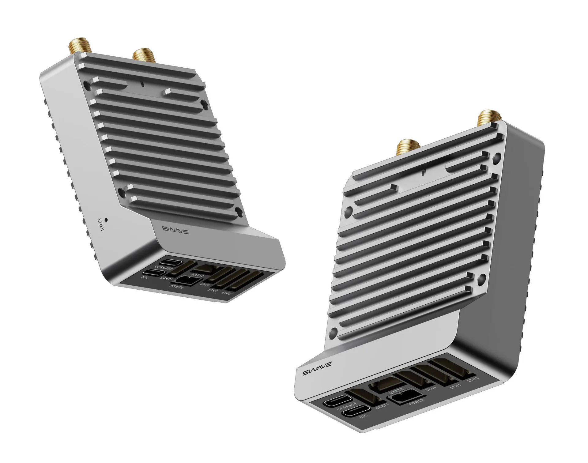
NEBULA-7 is an industrial video and data link module from Sinave Liaojiang Technology Innovation. It supports 800 MHz, 1.4 GHz and 2.4 GHz communication bands, combining high-speed data transfer, low-latency communication and flexible networking. It provides up to 30 Mbps of combined video and data throughput for unmanned system applications.
NEBULA-7 supports star networking and ad hoc networking for multi-node communication, relay forwarding and network self-healing, accommodating complex networks and long-range links. Dynamic frequency hopping (FHSS) and AES data encryption improve interference resistance and protect data. Configurable RF parameters and industrial interfaces simplify integration and deployment.
The system supports Windows, Android and Linux for remote control and video transmission from unmanned equipment. Ground station software such as QGC and Missionplanner can be used for formation missions.
Applications
NEBULA-7 supports unmanned systems and industrial wireless communication applications, including:
- Unmanned aerial vehicles (UAVs)
- Unmanned ground vehicles (UGVs)
- Robotic platforms
- Industrial wireless communication systems
System specifications
| System parameter | Specification | Notes |
|---|---|---|
| Operating bands | 2401.5–2481.5 MHz 1427.9–1447.9 MHz 806–826 MHz |
|
| RF channels | One transmit and two receive channels (1T2R) | |
| Transmit power | 2.4G / 1.4G / 800M: 25 dBm ±2 | |
| Network topology | Star network; up to 1+16 nodes | |
| Transmission range | 12 km air-to-ground with clear line of sight; up to 20 km with an optional panel antenna | |
| Channel bandwidth | 1.4 MHz / 3 MHz / 5 MHz / 10 MHz / 20 MHz | |
| Modulation | QPSK / 16QAM / 64QAM | |
| Maximum data rate | 30 Mbps shared between uplink and downlink | |
| Communication encryption | AES; password configurable in the PC software | |
| Transmission methods | Unicast, multicast and broadcast | |
| Latency | Startup latency ≤15 s Average one-way ping packet latency between two nodes ≤15 ms |
|
| Service interfaces | UART ×2 HSIC / USB (USB 2.0 High Speed) I2C, GPIO and others |
|
| Antenna connector | SMA-J | |
| Power control | Adaptive transmit power on access nodes Fixed transmit power on the central node |
|
| Transmission mode | Central-node downlink/uplink time-slot ratios: 2D3U / 3D2U / 4D1U / 1D4U |
|
| System control | Transmit power, frequency and bandwidth can be changed in real time | |
| Configuration management | WEBUI supports basic configuration, reporting and queries | |
| Interference handling | Dynamic frequency hopping | |
| Node modes | Automatic node, central node and access node | |
| Operating temperature | -25 ~ +75℃ | |
| Operating voltage | 5V ~ 26VDC | |
| Power consumption | Peak consumption below 5W | |
| Weight | 151g | |
| Dimensions | 64.5 X 73.6 X 18.4 mm |
RF specifications
| Parameter | Condition / band | Specification |
|---|---|---|
| Acquisition sensitivity | 2.4G | 20 MHz: -99 dBm 10 MHz: -103 dBm |
| 1.4G | 20 MHz: -99 dBm 10 MHz: -103 dBm |
|
| 800M | 20 MHz: -99 dBm 10 MHz: -103 dBm |
|
| Sensitivity (BLER ≤ 3%) | 2.4G | 20 MHz: -97 dBm (5 Mbps) 10 MHz: -96 dBm (5 Mbps) |
| 1.4G | 20 MHz: -97 dBm (5 Mbps) 10 MHz: -96 dBm (5 Mbps) |
|
| 800M | 20 MHz: -97 dBm (5 Mbps) 10 MHz: -97 dBm (5 Mbps) |
|
| Transmitter spurious emissions | BW = 1 kHz | < -36 dBm, 9 kHz ≤ f < 150 kHz |
| BW = 10 kHz | < -36 dBm, 150 kHz ≤ f < 30 MHz | |
| BW = 100 kHz | < -36 dBm, 30 MHz ≤ f < 1000 MHz | |
| BW = 1 MHz | < -36 dBm, 1 GHz ≤ f < 12.75 GHz | |
| Adjacent channel leakage ratio | ACLR | < -29.2 dBc @ E-UTRA1 < -32.2 dBc @ UTRA1 < -35.2 dBc @ UTRA2 |
Mechanical dimensions
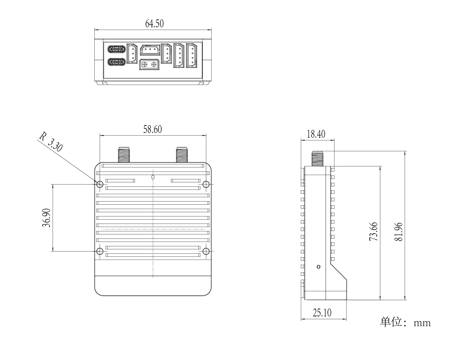 Chinese image placeholder. English replacement pending.
System application examples
Point-to-point communication
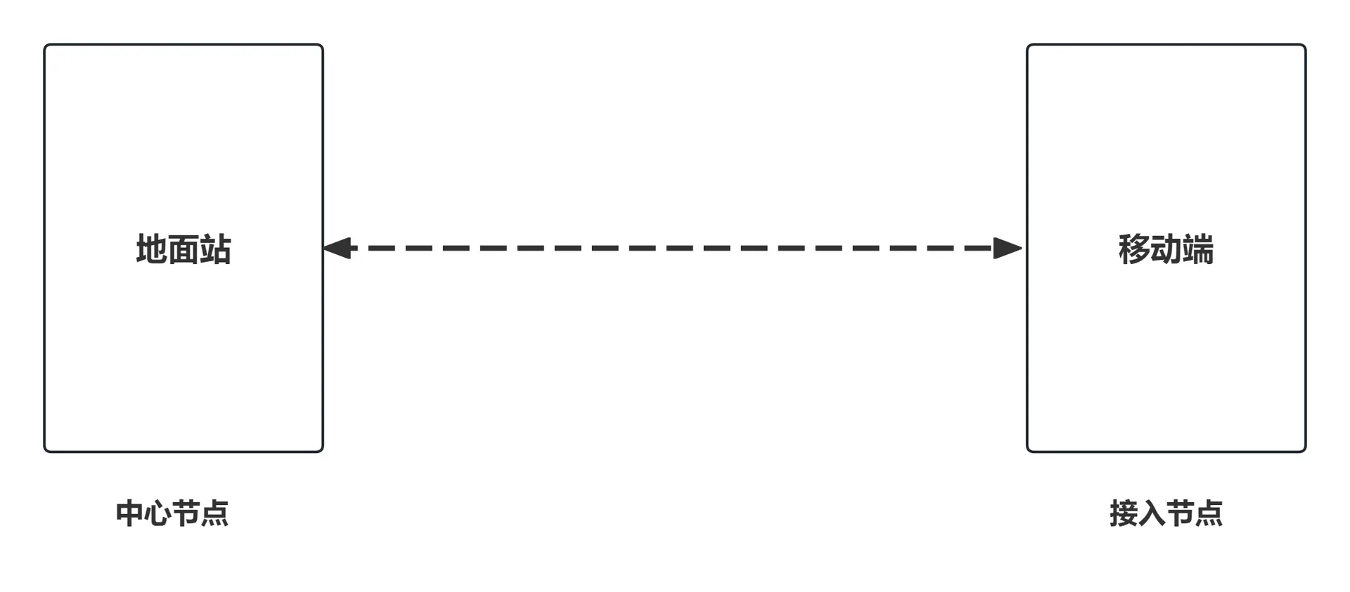 Chinese image placeholder. English replacement pending.
Formation communication
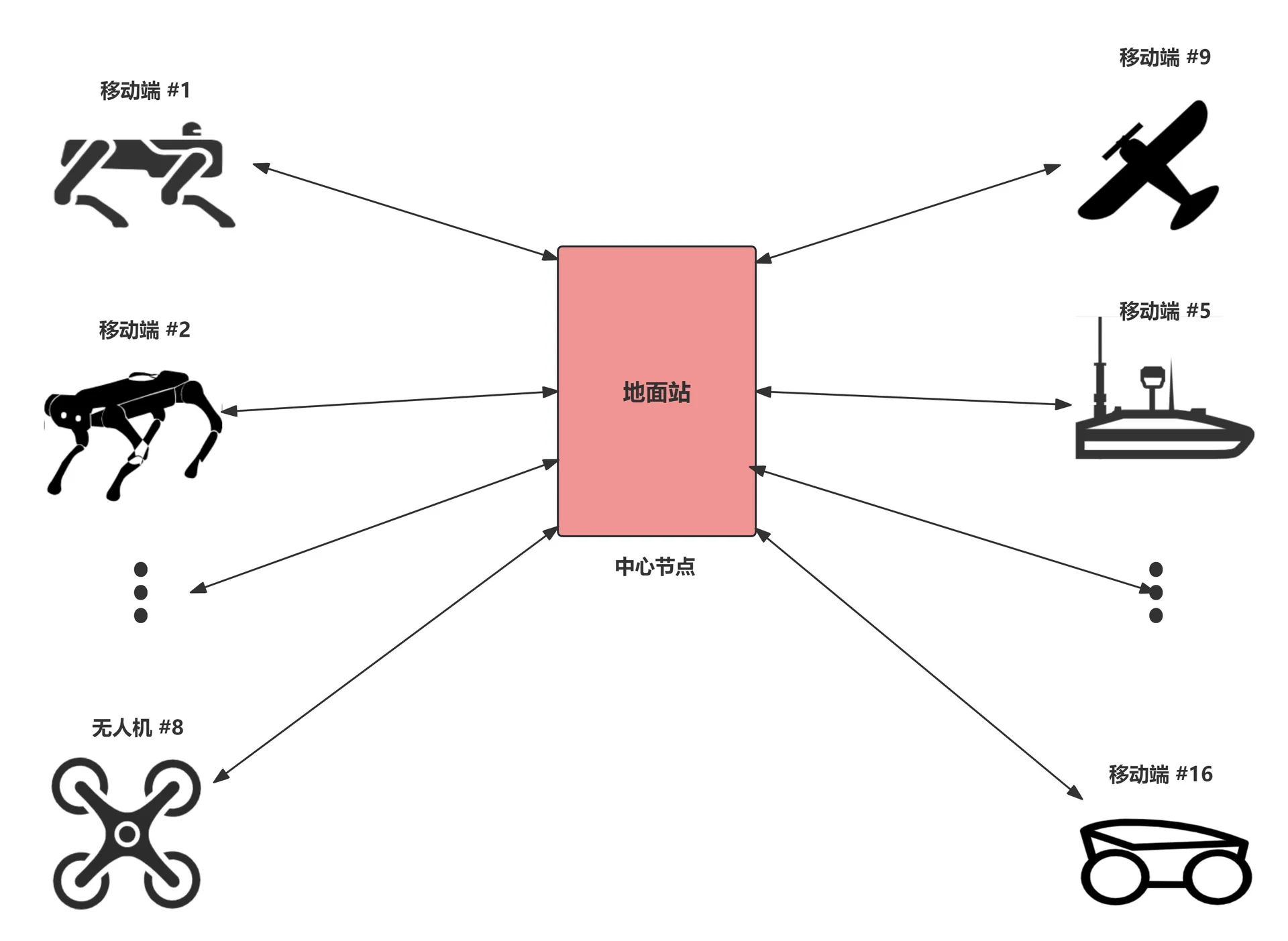 Chinese image placeholder. English replacement pending.
Interface definitions
Interface overview
NEBULA-7 provides the following interfaces for integration and expansion:
- 2 × Ethernet ports
- 2 × UART serial ports
- 1 × SBUS interface
The Ethernet ports support high-definition video transmission.
Serial data can be directed to a specified IP address, allowing connection to controllers, payloads and other external devices.
Pin assignments
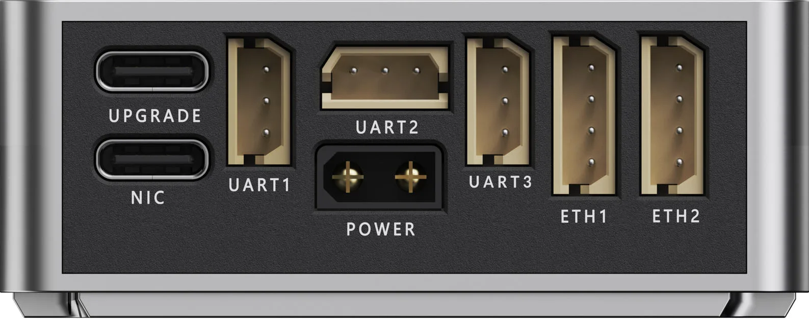
Ethernet harness definition
| Pin | Label | Type | Description |
|---|---|---|---|
| 1 | TX_P + | Differential transmit | Positive transmit signal |
| 2 | TX_N - | Differential transmit | Negative transmit signal |
| 3 | RX_P + | Differential receive | Positive receive signal |
| 4 | RX_N - | Differential receive | Negative receive signal |
Serial harness definition
| Pin | Label | Description | |
|---|---|---|---|
| 1 | GND | Signal ground | |
| 2 | RX | Serial receive | |
| 3 | TX | Serial transmit |
SBUS harness definition
| Pin | Label | Description | |
|---|---|---|---|
| 1 | GND | Signal ground | |
| 2 | NC | Not connected | |
| 3 | Sbus | Signal |
Hardware installation and wiring
Ground unit installation
Using the optional mounting bracket kit, tighten the four screws, attach the bracket's 5/8-inch nut fitting to the support pole, then insert the pole into the tripod. Install and tighten the selected antennas.
Starting the device without antennas may cause irreparable damage. Install the antennas before connecting power. The tripod is purchased separately. The device supports mounting on a pole with a diameter of 20–25 mm.
Installation procedure
1. Attach the mounting bracket
Align the mounting bracket with the communication module. Insert the four screws (M3*22) and tighten them evenly. Check that the module is securely mounted and does not move.
2. Attach the support pole
Align the bracket's 5/8-inch nut fitting with the threaded end of the support pole. Screw it clockwise and tighten it. Keep the connection secure and coaxial, without tilt or play.
3. Mount the tripod
Insert the assembled support pole into the tripod socket. Secure it using the tripod's latch or locking knob. Adjust the leg spread so the assembly is stable.
4. Install the antennas
Select an antenna type for the application:
- Fiberglass antenna: long-range links and fixed deployments.
- Rubber-duck antenna: portable or short-range applications.
- Panel antenna: very long-range applications; can be used with an antenna tracking mount.
Align the antenna connector with the device's SMA connector and tighten it clockwise to ensure good contact. A wrench may be used to secure it.
5. Check the installation
Confirm that:
- All screws are tight.
- Threaded connections are secure and do not move.
- Antennas are upright and do not wobble.
- The tripod provides stable support.
Connect power only after these checks are complete.
The completed installation is shown in the illustration.
Installation precautions
- Do not use excessive force that could damage threads.
- Do not tilt the antennas or repeatedly twist them during installation.
- Place the tripod on level ground when operating outdoors.
- Do not operate in strong winds unless the equipment is properly secured.
Air unit wiring
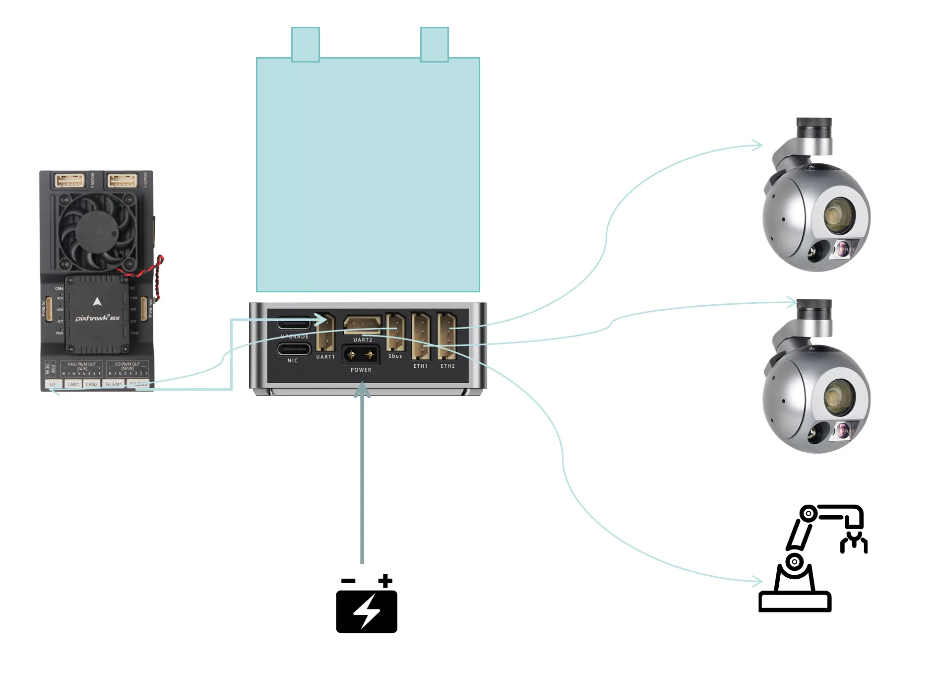
NOTE: Network cameras and ROS devices must be on the same subnet as the NEBULA-7 link, for example 192.168.1.X. Every device must have a unique IP address. To change an IP address, follow the supplier's tutorial or consult technical support.
Ground unit wiring
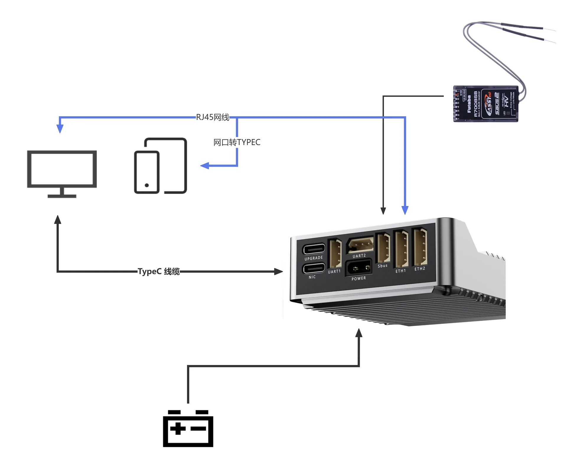 Chinese image placeholder. English replacement pending.
Indicator definitions
| No. | LED pattern | Meaning |
|---|---|---|
| 1 | Steady red | Preparing to start |
| 2 | Single red flash | Standby; ready to pair |
| 3 | Single red flash and single green flash | Pairing successful; a single green flash indicates one paired module |
| 4 | Single red flash and double green flash | Pairing successful; a double green flash indicates two paired modules |
First use
Connecting a Windows computer
1. USB connection
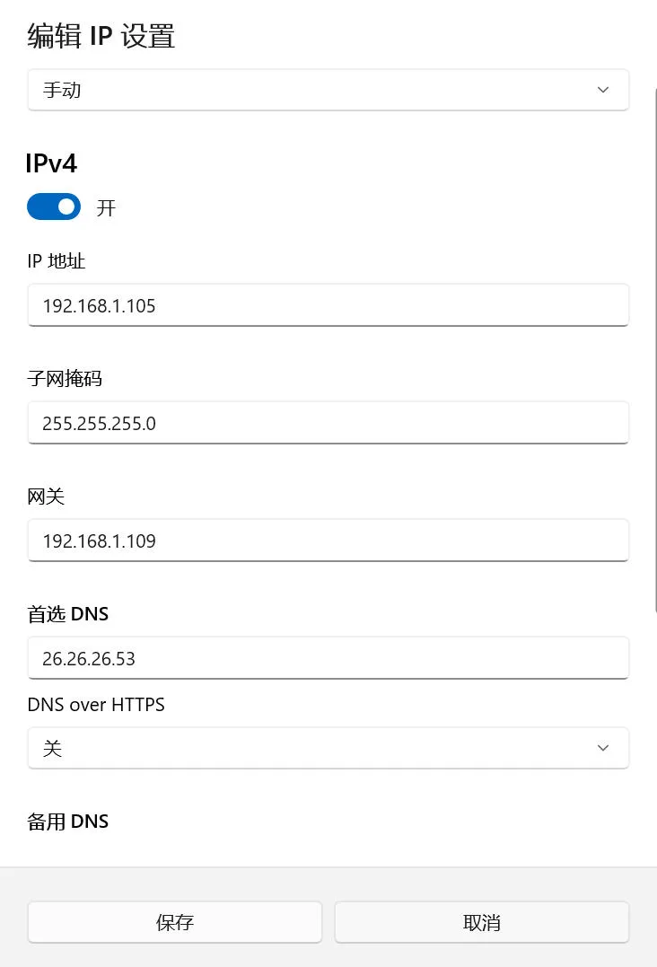
Connect a USB-C cable to the communication module's NIC port. Install the required driver and configure a static IP address on the computer, for example 192.168.1.X.
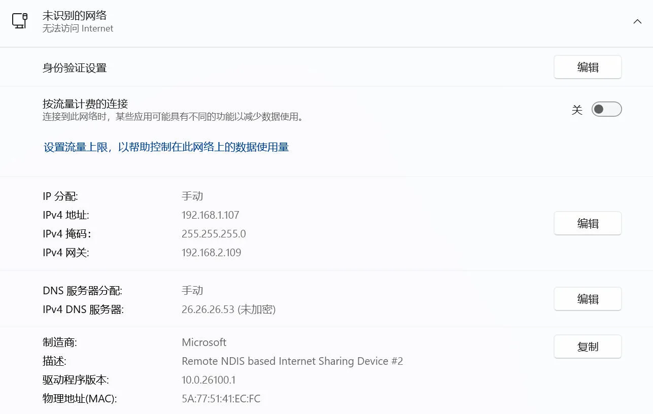 Chinese image placeholder. English replacement pending.
2. Ethernet connection
Connect the computer to ETH1 or ETH2 using an Ethernet cable. Configure a static IP address on the computer, for example 192.168.1.X.
 Chinese image placeholder. English replacement pending.
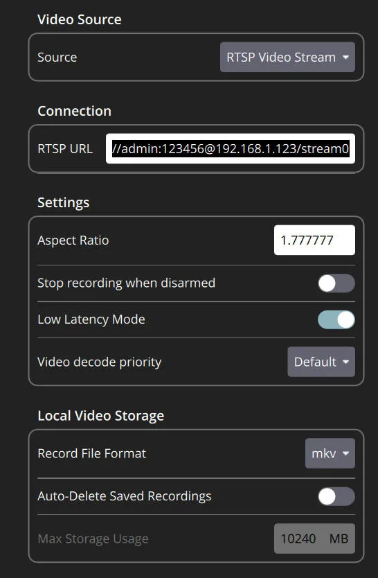
3. Configure an RTSP video stream (QGC or another player)
Configure the RTSP stream in the ground station or video player. Example URL format:
rtsp://<username>:<password>@<camera-ip>/stream0
Replace the placeholders with the camera's credentials and IP address.
4. Configure the camera network
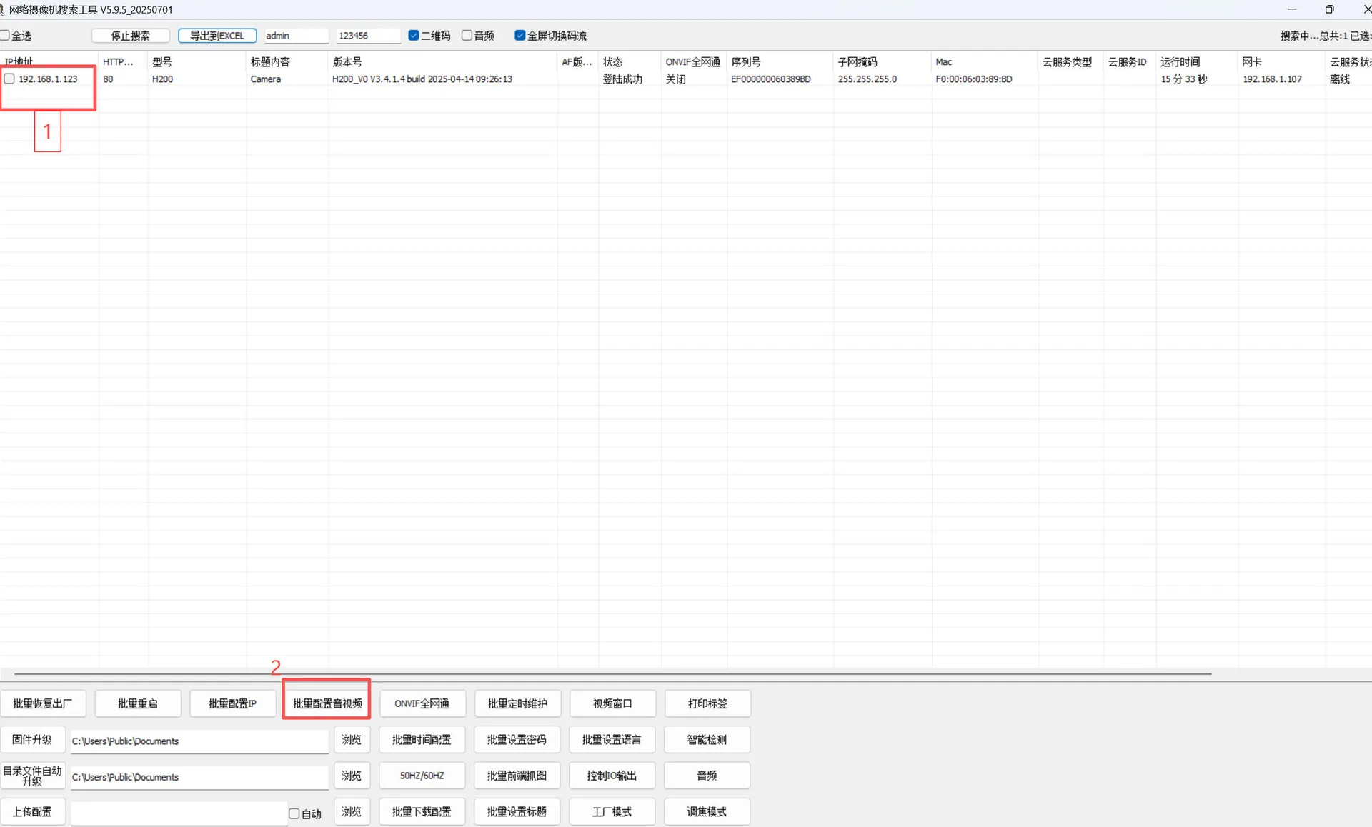
The air unit's camera must be on the same subnet as the communication module; otherwise, video cannot be transmitted correctly.
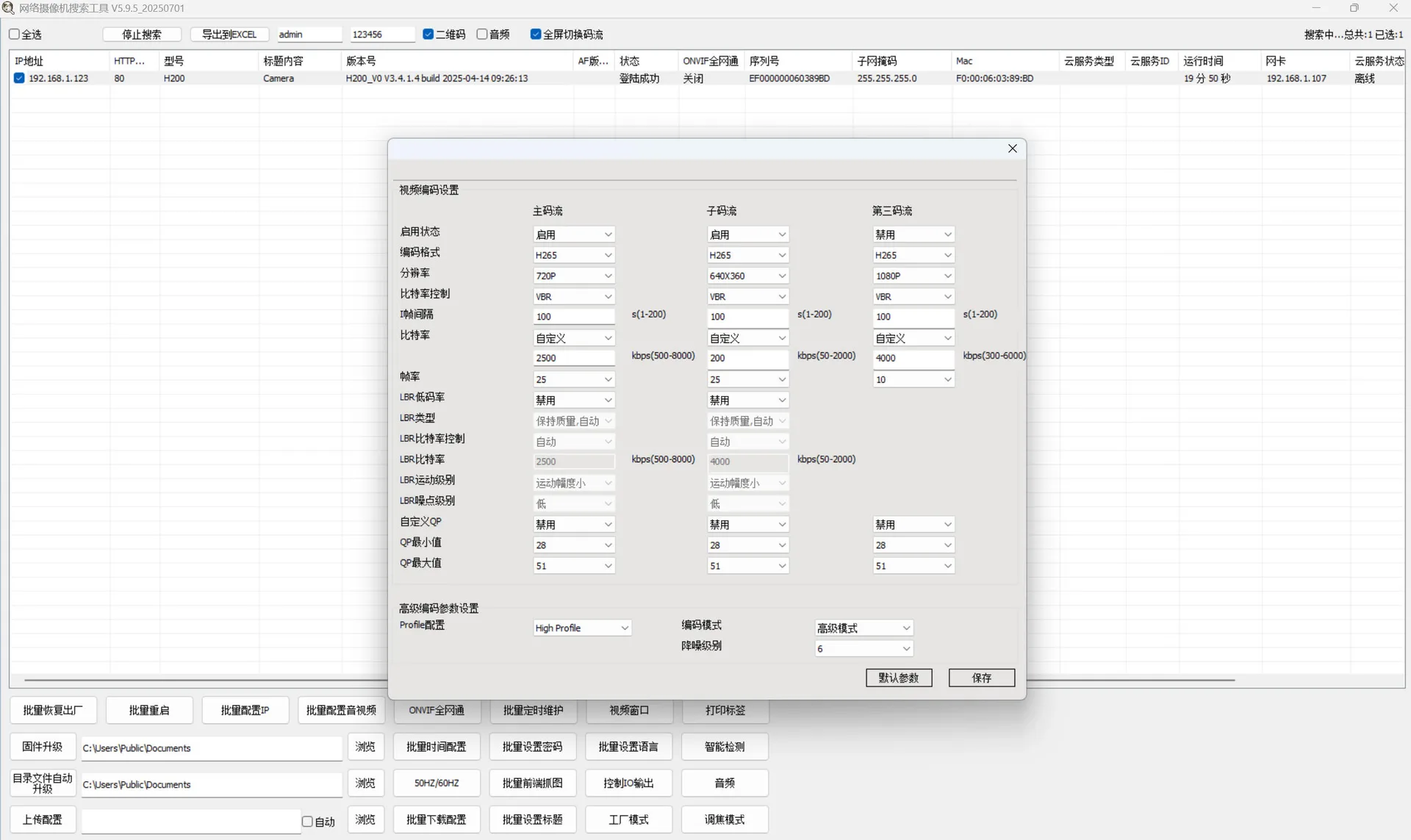
Use IPC Tools to configure:
- Camera IP address
- Resolution (720P / 1080P)
- Frame rate and other parameters
 Chinese image placeholder. English replacement pending.
 Chinese image placeholder. English replacement pending.
Connecting an Android tablet
1. Hardware connection
Connect the communication module's ETH port to the tablet using an Ethernet-to-USB adapter.
2. Enable wired networking
Open the device settings and select Wired network.
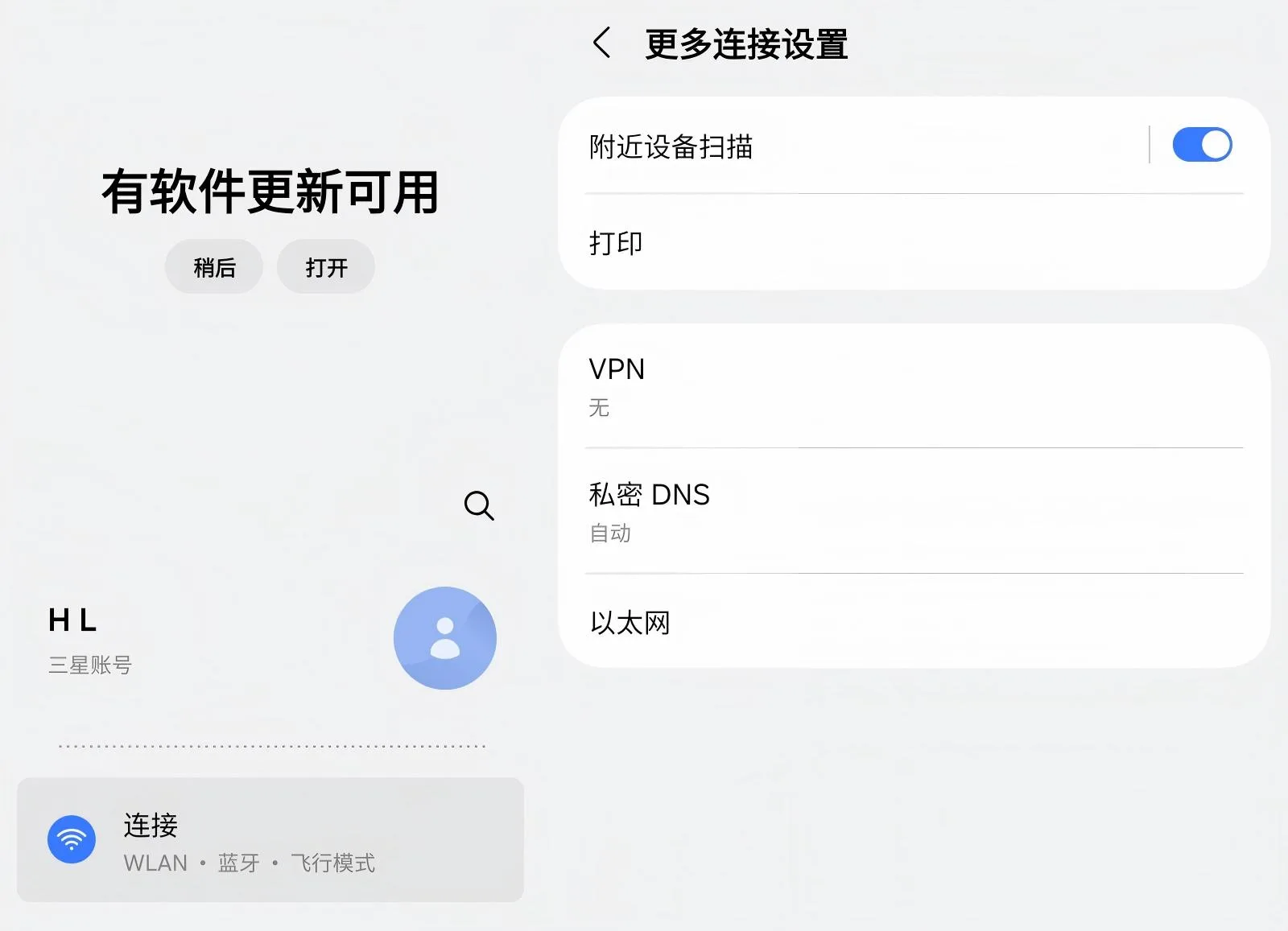 Chinese image placeholder. English replacement pending.
3. Configure a static IP address
Set the tablet's IP address manually, keeping it on the same subnet as the communication module.
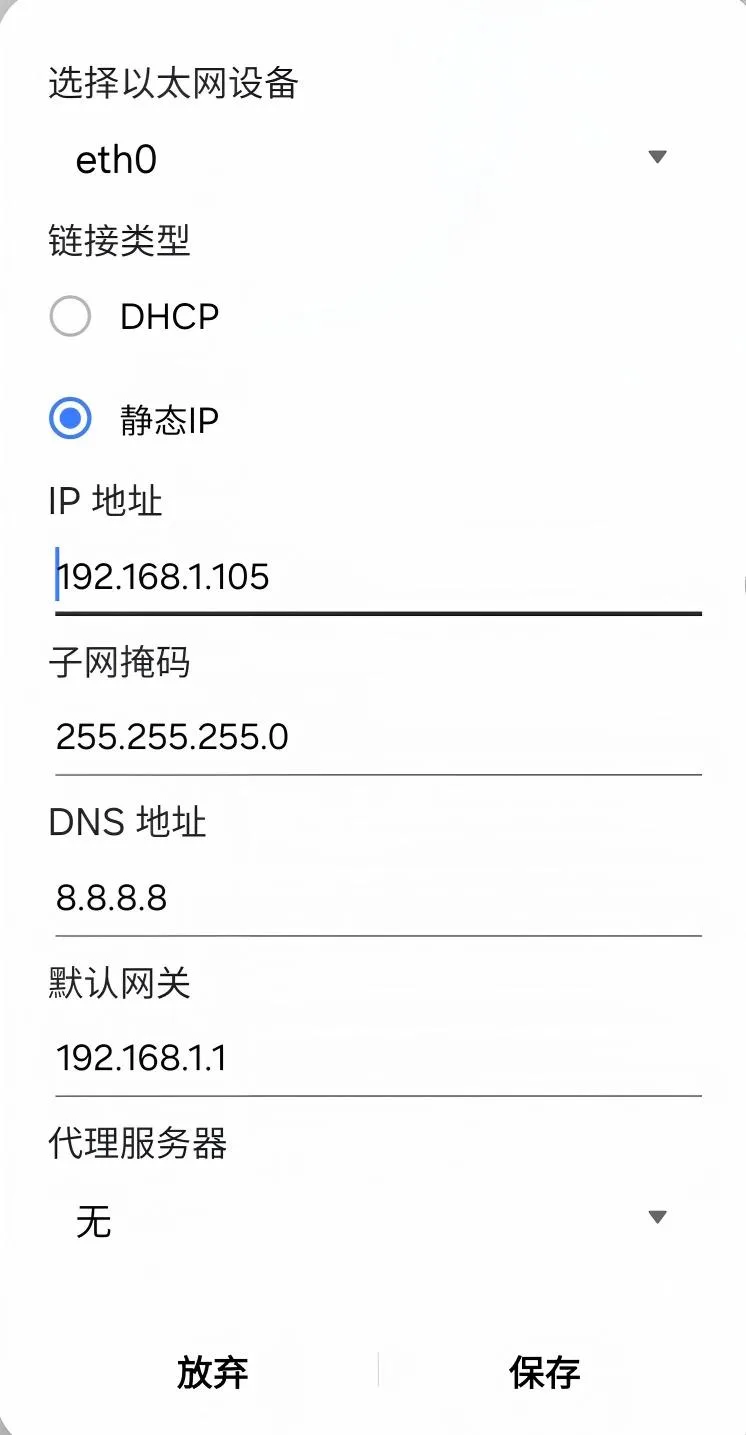 Chinese image placeholder. English replacement pending.
4. Configure video in QGC
Open QGC and enter the corresponding port to view the video stream on the main screen.
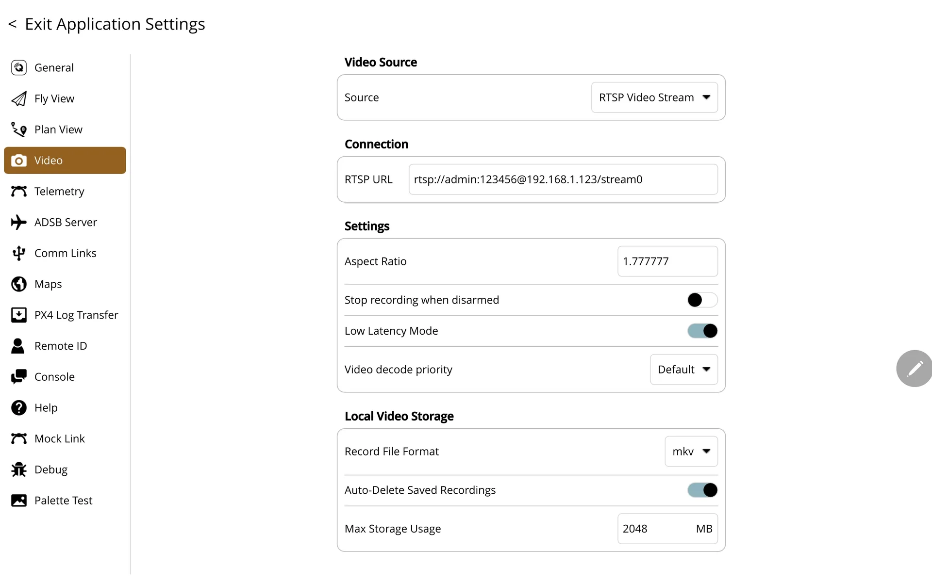
5. Configure the flight controller data link (UDP)
When configuring the flight controller data link:
- Select UDP connection mode.
- The port must match the communication module's remote port, for example 14551.
- In a multi-node network, assign a separate port to each access node to prevent conflicts.
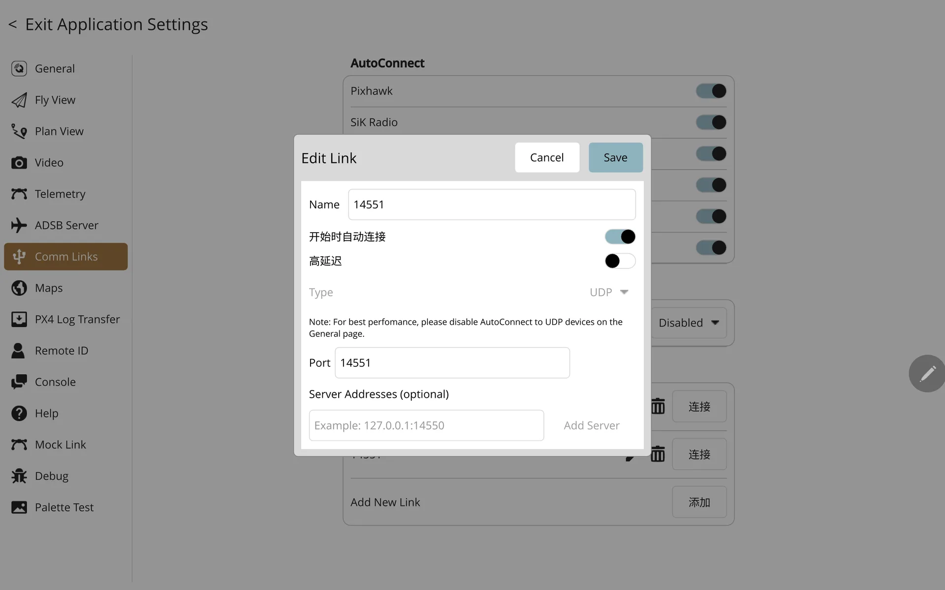 Chinese image placeholder. English replacement pending.
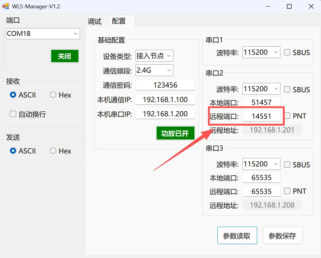 Chinese image placeholder. English replacement pending.
WLS Manager configuration
WLS Manager software
NEBULA-7 includes graphical PC software for link configuration, network settings and status monitoring.
The graphical interface simplifies configuration, debugging and deployment.
Download: WLS Manager configuration software
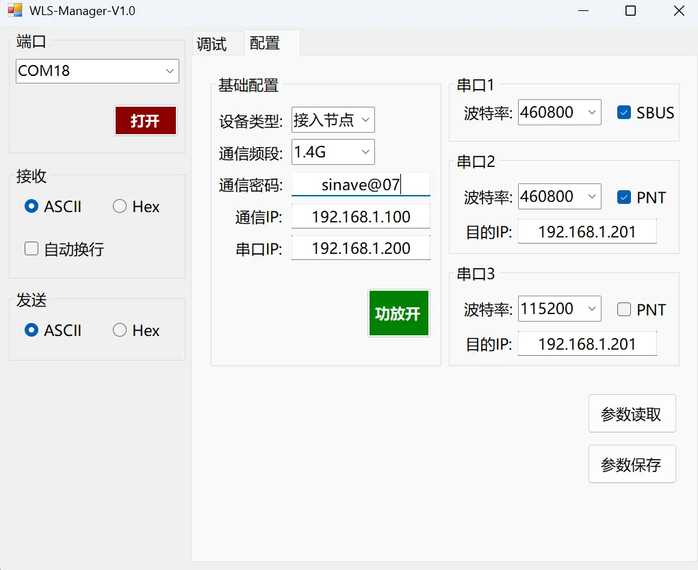 Chinese image placeholder. English replacement pending.
Find the communication module's serial port in Device Manager. Select that port and click Open to connect. Once connected, click Read parameters. The software retrieves all current settings from the module and displays them for inspection and editing.
Configuration workflow
1. Read parameters
- On the configuration page, click Read parameters first.
- If some parameters have not loaded, repeat the operation until all values are available.
2. Write parameters
- After editing a parameter, press Enter to write it.
- The software reports whether the write succeeded or failed.
3. Save parameters
- After completing changes, click Save parameters.
- Unsaved changes are lost when the device loses power or restarts.
4. Apply parameters
- After saving, power-cycle the device for the parameters to take effect.
Parameter descriptions
1. Device type
- Central node: the core node of a star network.
- Access node: connects to the central node as a subordinate node.
- Turn off the power amplifier before changing parameters.
2. Communication band
Supported bands: 800MHz / 1.4GHz / 2.4GHz.
- Turn off the power amplifier before changing parameters.
- Select an antenna that matches the frequency band.
- The supplied omnidirectional rubber-duck antenna supports all bands.
3. Communication password
- Supports a custom, case-sensitive password containing numbers and symbols.
- Uses AES encryption to protect communications.
4. Communication IP (ETH)
- Configure the Ethernet interface's network parameters.
- IP addresses must be on the same subnet and must not conflict.
5. Serial IP (UART)
- Configure the network parameters for serial communication.
- Each IP address must be unique to avoid conflicts.
6. Serial port 1
- Configure the baud rate.
- Broadcast mode is the default and cannot be changed.
- Supports SBUS mode.
7. Serial port 2
- Configure the baud rate and destination IP for directed transmission.
Operating modes:
- Point-to-point mode (PNT)
- Select PNT.
- Communicate one-to-one only with the specified remote IP address and port.
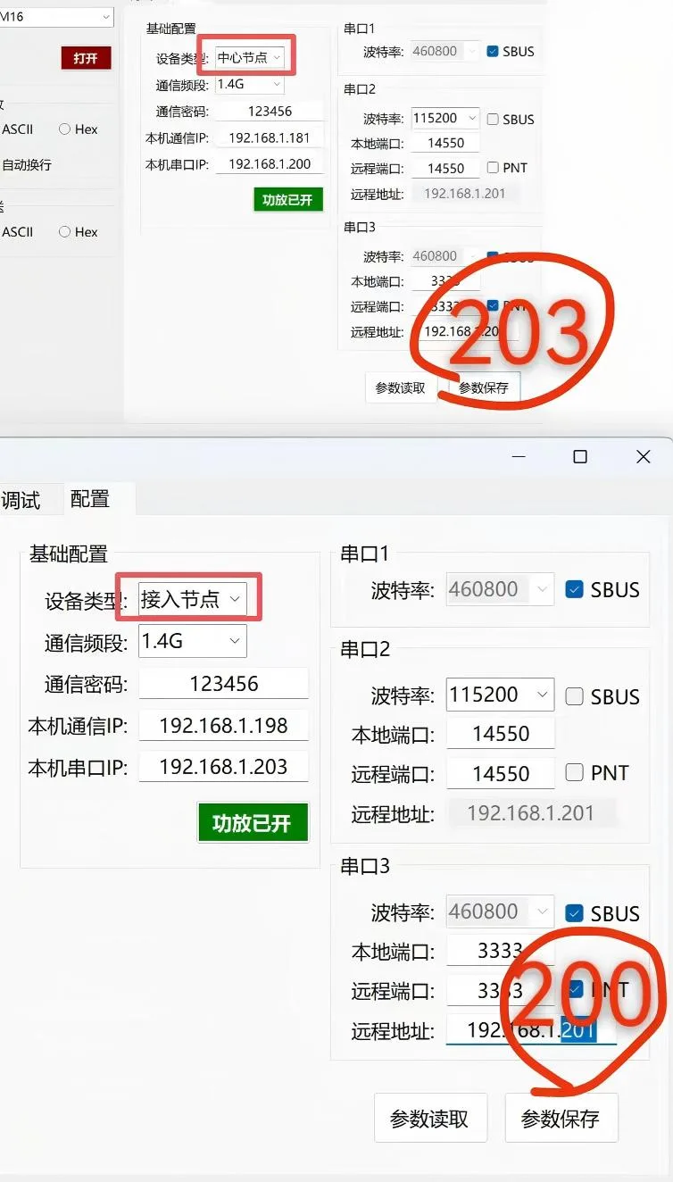 Chinese image placeholder. English replacement pending.
- Service mode (non-PNT)
- Clear PNT.
- No remote address needs to be configured.
- Communication with any remote device is supported.
- The local and remote ports are the same.
8. Serial port 3
The functions are the same as serial port 2.
9. Read parameters
Read the device's current configuration and refresh the display.
10. Save parameters
Save the current configuration.
⚠️ Unsaved parameters are lost after a power interruption or restart.
11. Power amplifier control
- Power amplifier on: enable the power amplifier.
- Power amplifier off: disable the power amplifier. It must be off when changing parameters.